Roller Lower Control Arms - LCAs
This 'how to' was published on fordmuscle.com. Check it out here: http://www.fordmuscle.com/forums/tech-exchange/481020-roller-lower-control-arms-lcas.html
This is another great addition to my 'Best Bang for the Buck' suspension project. I saw a article on FordMuscle.com about some Opentracker roller LCAs. I figured since the Roller Perches worked out so well that I wanted a set of these. However, I didn't have the money to buy the kit at the time so I looked for a less expensive way to upgrade my LCAs.
A friend of mine showed me how he made his roller perches. He design was simular to Opentrackers but more DIY which worked out pretty good for me.
For this project I decided that I was going to use my current LCAs as donors for my Roller LCA project since my car was up on stands anyway. To do this I figured I had three problems:
1. Balljoints: The balljoints certainly need to be replaced if I am going to rebuild the arms.
2. How to do the roller bearings: If I couldn't afford the Opentracker kit what were my options.
3. Boxings the arms: Is this needed and what do I use to do it with.
Lets start with the build and deal with the problems as we go.
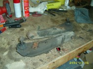
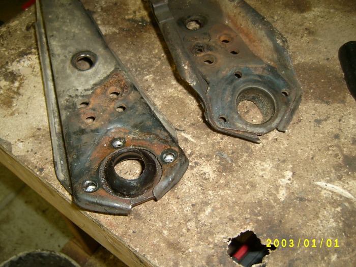
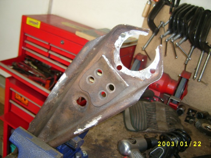
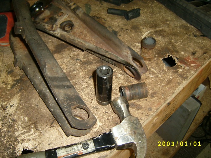
First thing to do with your donor set of LCAs is to inspect them to make sure that they are a good donor set. be sure that they are sounds.
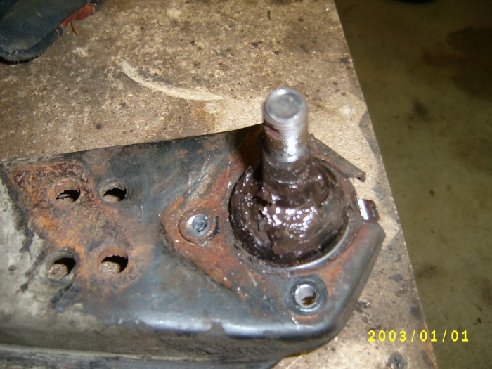
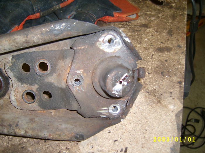
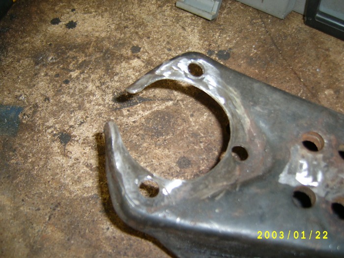
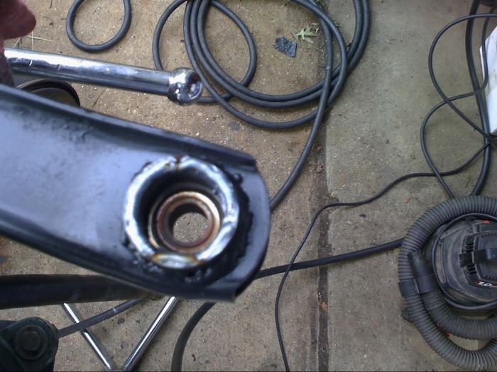
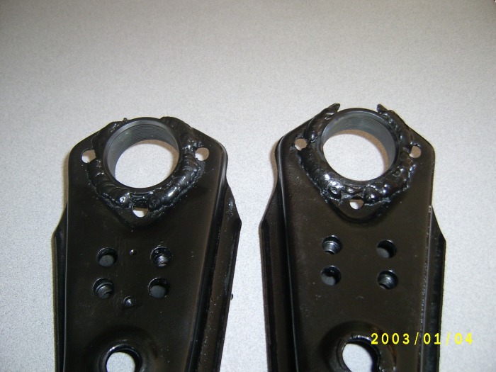
Then we must remove the old ball joints. Drill out the three rivets that hold the ball joint in place. Pry the tops of them off and this will expose the ball joint case. Then pry the bottom of the ball joint from the frame. You just want to pry it down some. I decided that I wanted to keep the area in tact where the strut rods bolt to the LCA. This plate is welded in place here and is the correct thickness for the strut rod bolts. This entire ball joint plate/cup thing does not provide the strength in the LCA so it is OK to remove it. The easy way for me to do this was to use a 4" cut off wheel. While you are at it you might want to clean up this end of the control arm.
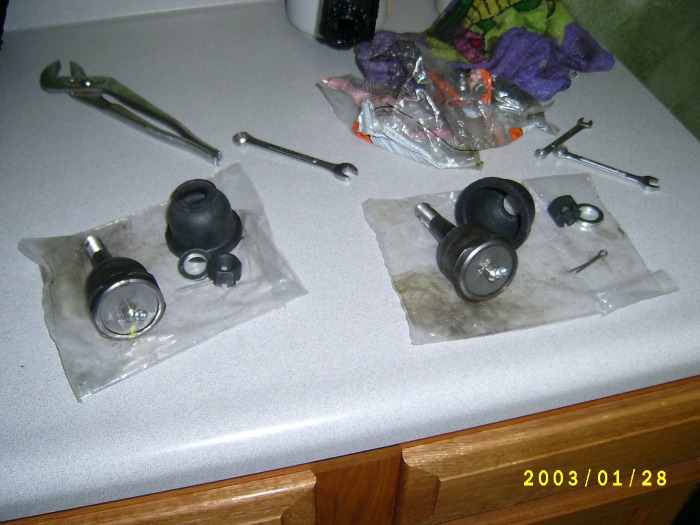
Now to deal with problem 1. I need new ball joints. I spoke to Opentracker about this and he was very helpful. He provided me with the following information on the ball joints that he uses for his LCAs.:
"For maximum performance and serviceability I recommend screw in ball joints. I use Afco (www.afabcorp.com) ball-joint #20034 and #20043 threaded sleeve. The sleeve must be welded into your arms. I do this modification on OpenTracker Racing Products track series arms." ~ Opentracker
AFCO: BALL JOINT - UPPER
AFCO: SLEEVE - SMALL THREADED
Taking this advice on the balljoints I asked around a little and found a couple forum friends that had used them and got a thumbs up so I went a head and ordered a set. My costs:
Balljoints = $16.12 each x 2 = $32.24
Sleeves = $11.22 each x 2 = $22.44
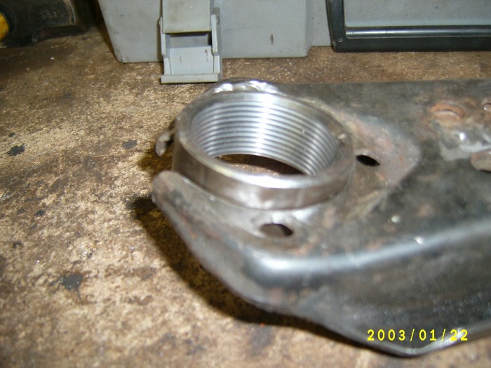
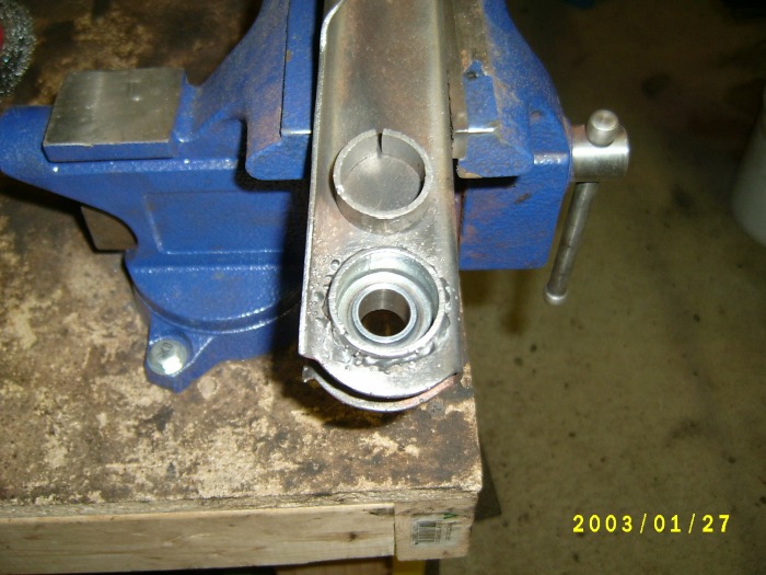
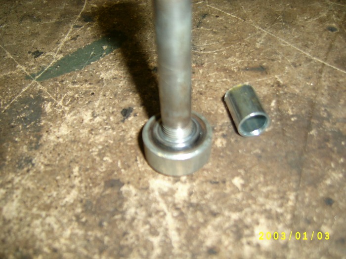
Now to get them installed. I traced the sleeve on the end of the control arm with a scribe. You could use a nail or a screw driver if you wanted. Then I took my trusty 4" cutter and carefully grind out the traced portion of the arm and did several test fits of the sleeve. Once everything was perfect I used a magnet and a couple of spacers (you can use what ever you have for spacers as long as you get it even) to set the sleeve in place. Then used my mig with a couple of tacks to hold the sleeve in place. Then checked to be sure I was happy with how the sleeve was spaced. I wanted it about a 1/3 of a inch above the control arm. Then I welded it into place. The welds aren't pretty but they are strong (flux welds aren't pretty). Weld this from both the top and the bottom. If you are not sure about your welding source this out.
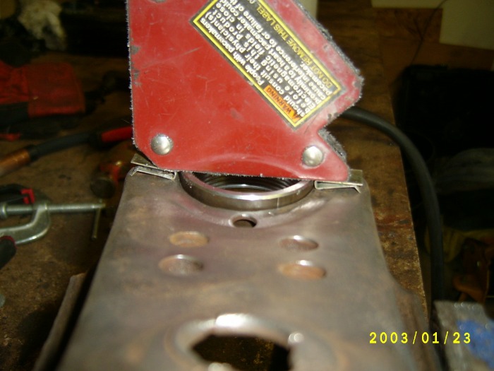


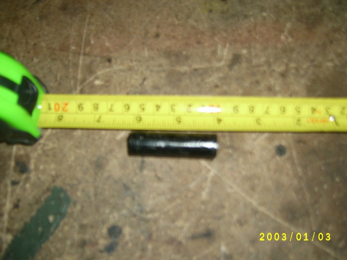
Now with the sleeve in place it is time to look at the roller part of the project. This is where Tweet66 comes in. He provided me with the information to get this done easily. The first thing you need to do is remove the sleeve and rubber bushings that are in the arm now. To do this I think the easiest way is to burn them out. Use a propane torch and melt them/set them on fire and you will be done in no time. When the bushing is good and hot with a flame take some pliers and simply pull the sleeves out. Don't damage these sleeves as they are going to be reused with the roller arms. Here you can see the bushing is still in flames and the sleeve is smoking hot!!
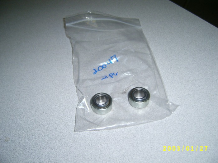
Now to deal with problem number 2. The roller bearing. I spoke with Tweet66 and he was kind enough to show me how he solved this problem. The first thing was that he used the following roller bearings: http://www.midwestcontrol.com/buy.php?item=2439
These cost me $6.28 each for a total of $12.56 plus shipping. These bearing are sound and are backed with some pretty good specs. I don't believe I will have any issues with these. The next part of this step is to get them into the control arms. This is what Tweet66 did, so this is what I did:
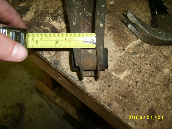
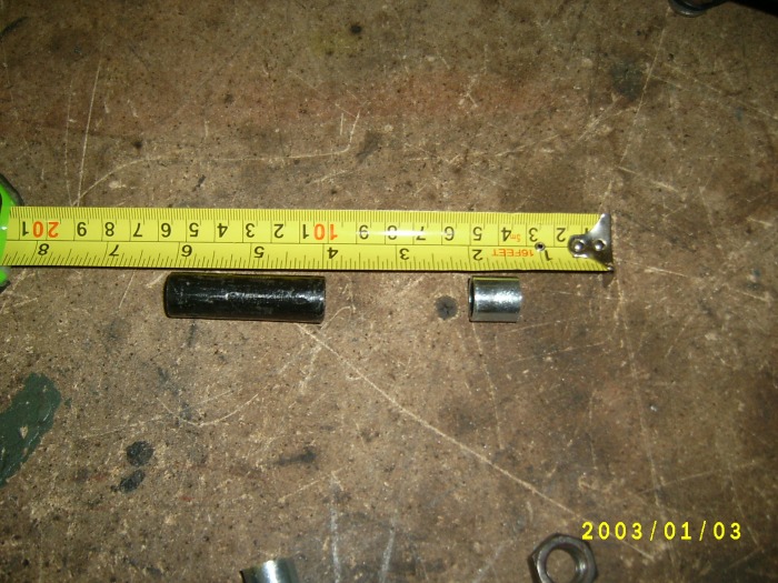
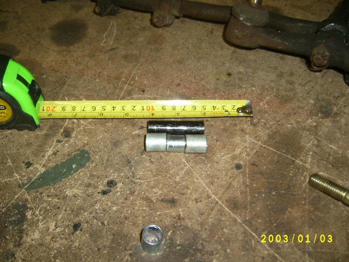
Following Tweets instructions I pressed out the bushing outer sleeve. This wasn't hard to do. I used a socket that matched the size and a rubber mallet. Some whacks with a hammer and they were free of the control arm. Now I did measure the distance between the sides of the arm before and after to be sure I didn't mangle up the arms when I beat the sleeve out. Lucky for me no harm was done.
The tubing that Tweet uses is slightly larger than the bearings outside diameter. Since I didn't have any of this tubing I asked Tweet if he could provide me with the tubing for a small fee. $20 later I had some coming in the mail.
Tweets details:
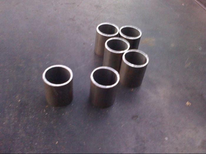
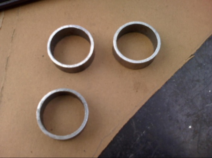
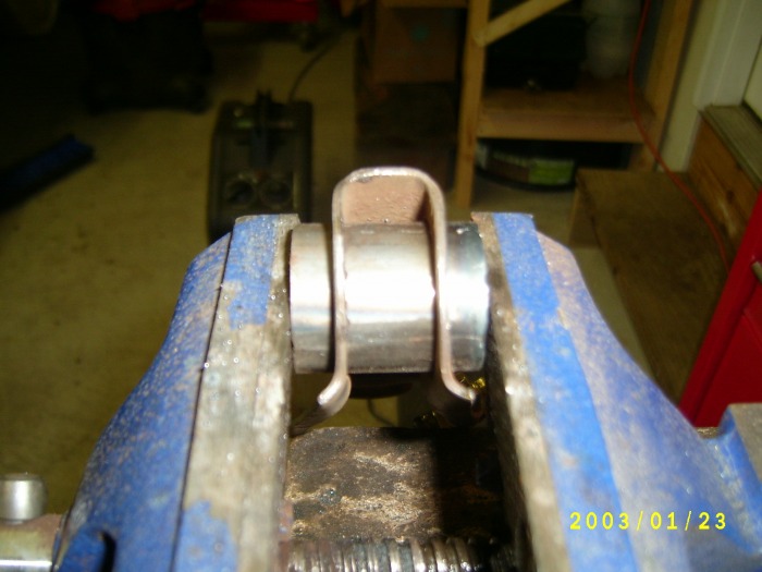
-This is the tubing I used for the new bearing race. It’s slightly larger than the bearing’s outside dia.
- Cut into 1 ½” long pieces.
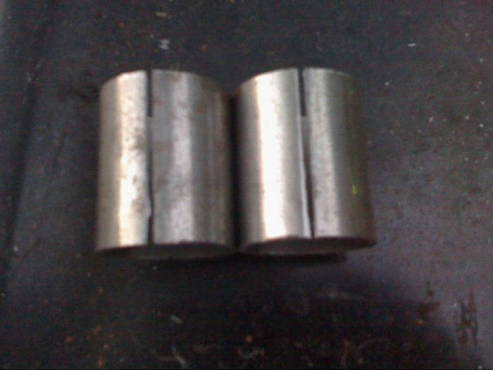
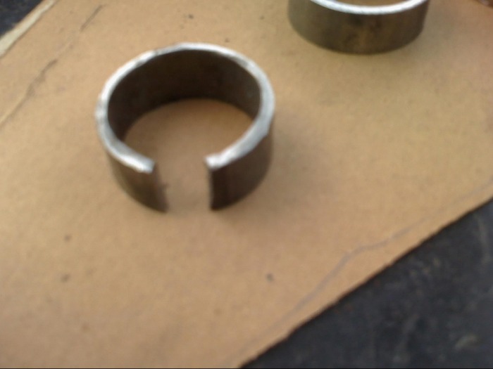
- Because the inside dia. Is slightly larger than the bearing and you want a tight fit cut slots in the tubing. I run the slice over my bench grinder at an angle to bevel the edges and remove a little more material.
- Here’s the tube welded back together. The easiest way to accomplish this is to place it in a vice or a set of large vice-grips (my choice) and squeeze the tube closed. The bevel from the grinder will allow good weld penetration.
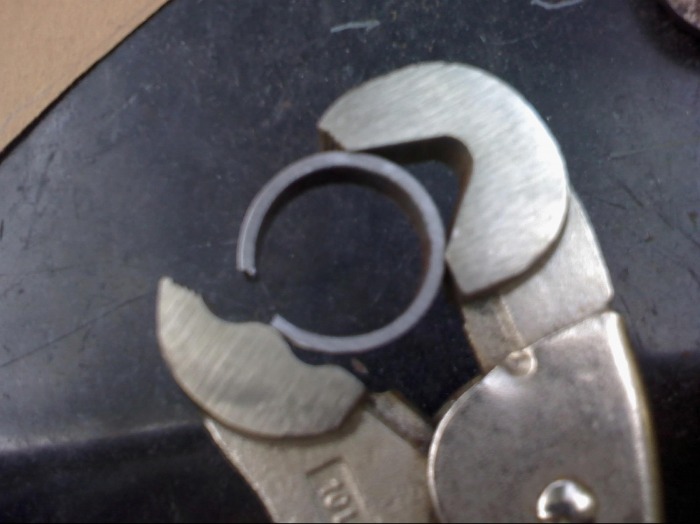
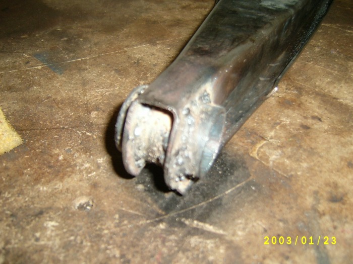
-Next cut more of the tubing for the bearing retainers
- Cut slices in the retainers so they can be squeezed into the sleeve.
- Squeeze the retainers to a smaller diameter. Vice grips and patience seem to be the best way to do this.
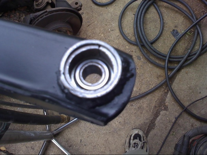
- Test fit the bearings and the retainers on the sleeve in the arm.
- Weld the retainers onto the sleeves. Be careful not to get any weld on the bearings.
Tweet66 pictures below:
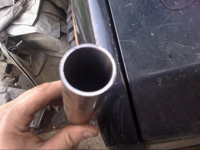

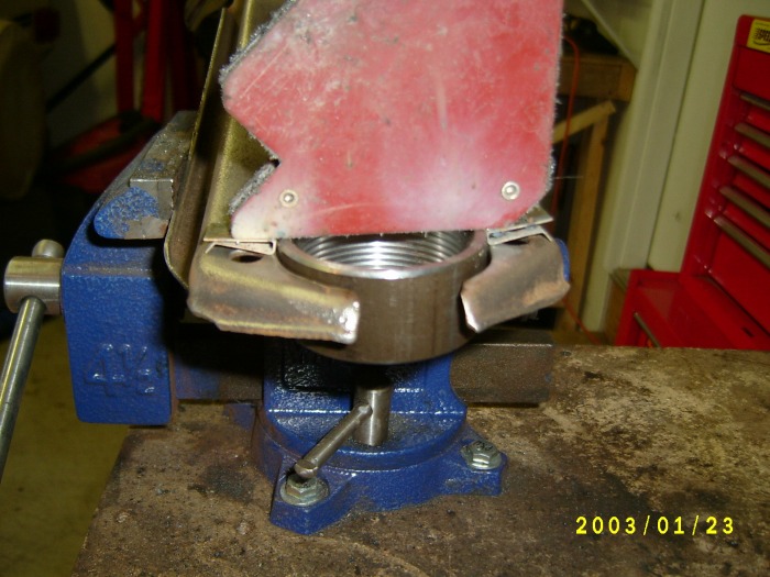
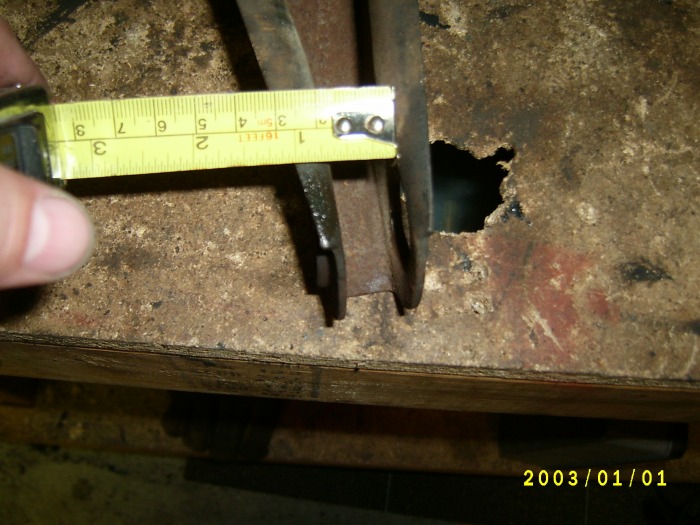
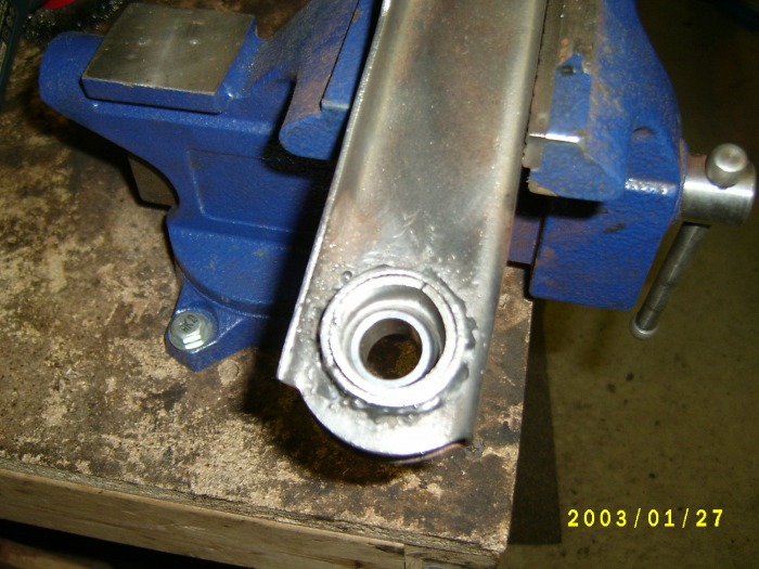
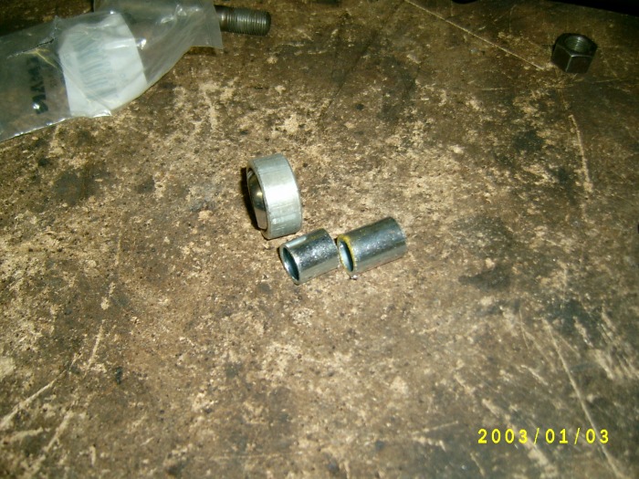
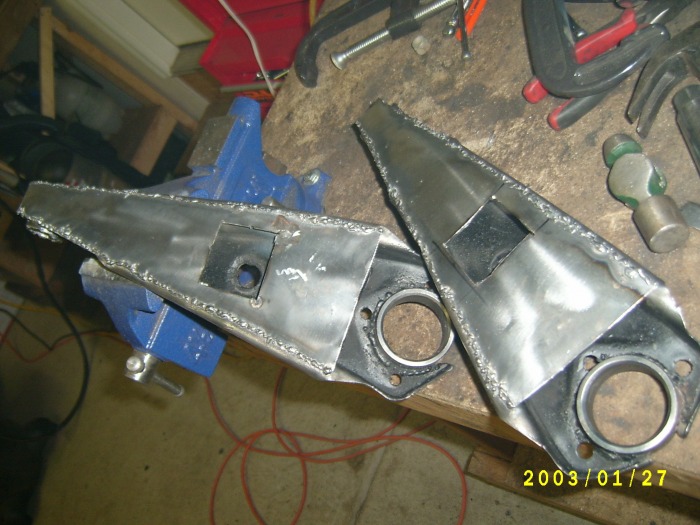
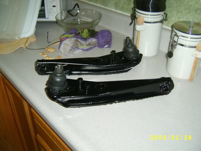
So with that in mind and my tubing from Tweet in hand I got back to it. Time to put the tubing in place. Now that I have the sleeve and the outter sleeve out of my control arms I took my new outer sleeve that I got from Tweet (see middle pic above) I traced it with a scribe like I did the sleeve. Now I didn't have any cutting wheels left for my drumell so I took a pair of side cutters and cut a 4" wheel down to 2" or so and used that. Worked great. I carefully cut away the metal to the traced line and did several test fits of the outer sleeve until I was happy. Then I put the sleeve in the arm and put the whole thing in my vise. Centered it and tacked it in place. Did a double check to make sure all is well. Then I proceeded to weld it in place. I still need to clean up the flux mess but the welds are solid.

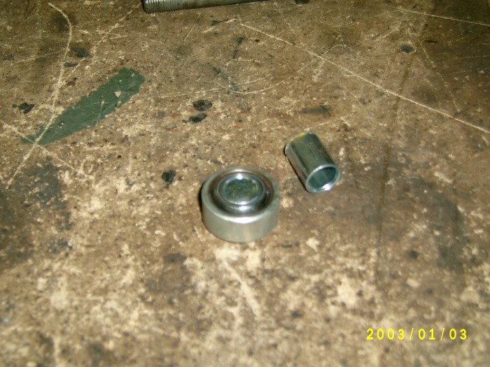
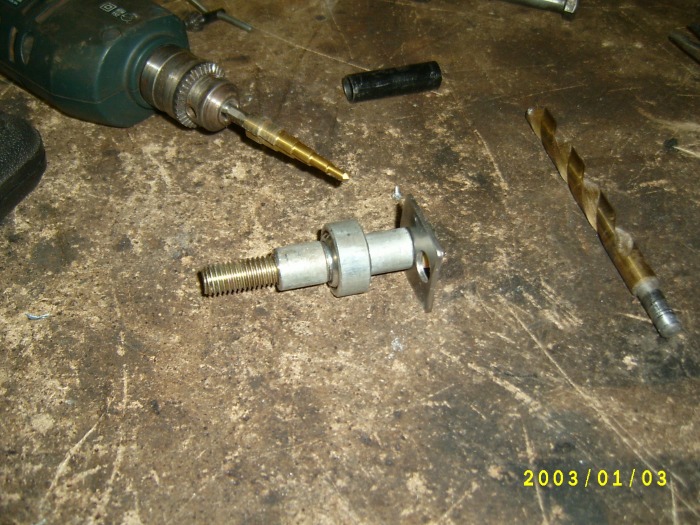
So I finally got my bearings. So now it was time to clean up the inner sleeves and tweak them to fit in the bearings. I was using my bench grinder but it was not working well so I came up with something better. I used my side grinder in my bench vise and it worked great. I would grind some and test fit, over and over each time doing just a little. You only want to take off what you need. Not to much. This requires lots of fit tests. This took about 20 min to do both sleeves. While I was at it I also did a test fit with the bearing and the outer sleeve that has already been welding in the arms. Fits like a glove! Then I put in the retainer and used a socket that was the same size as the retainer and gently tapped it down until it was up against the bearing so the bearing has no side to side play. Ready for welding. Now to protect the bearing from the weld etc. I took a old bumper bolt that I had and put it in the sleeve top down and went a head and did my welds.

I totally forgot to add this part earlier. Sorry.
There is a sleeve that I pulled out and took down in size so it would fit through the bearing. I thought that this was all that was needed for this. However, I was wrong. I soon discovered that with this set up there was nothing to keep the arm from sliding side to side on the sleeve once it is mounted on the car. I spoke to Tweet66 and he confirmed this.
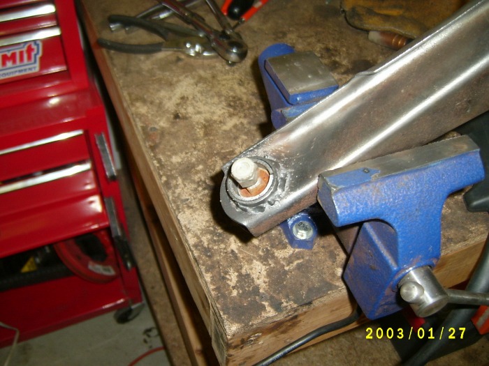
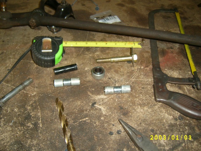
So I took a trip down to the local Lowes and got a sleeve that is 1/2" inside but still fit in the bearing (we will call this the bearing sleeve) and then I got some pipe that was also about 1/2" inside but would not fit inside the bearing (we will call this the bearing stop) but was not overly huge to cause bind in the bearing movement.
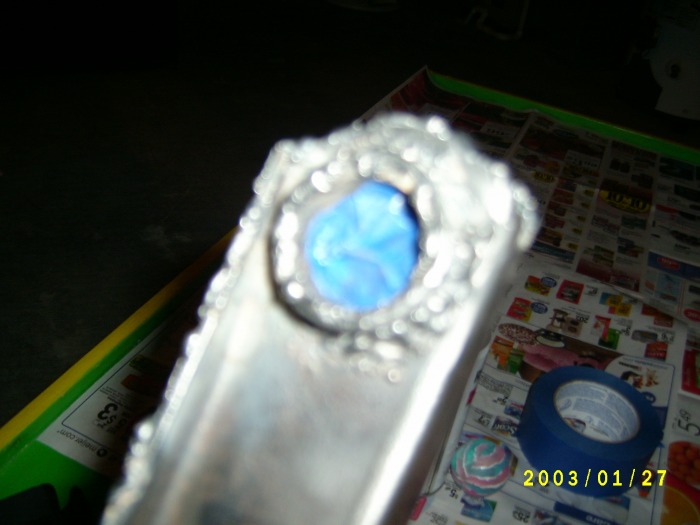
I measured the original sleeve that came out of the rubber bushing. It measures 2 inches. Then I trimmed the bearing sleeve so it was as long as the bearing that it is sliding into. This is just over 1/2". then I took the pipe and cut two 3/4" sleeves. Held them all together to make sure that together they measured 2". I used a cutting/grinding stone to make the final adjustments. Then I took my cool drill bit and drilled out the inside of the bearing stops to a true 1/2" so my bolts will fit with out issue.
After all that (which only took about 20 min) I was able to slide the bearing sleeve into the bearing, then put each of the bearing stops into the arm, one on each side, put the arm in please in the mount on the car with the bearings ready to accept the bolt. Slide the bolt through and all was done. There is no side to side movement at all which is the point. I think the pictures will fill in any missing details.

Now to deal with problem 3. This is the point where if I wanted to be I could be done. I had emailed Opentracker and asked if boxing these LCAs was required. His response:
"you don't need any bracing on the street. We ran our first three years of open track events with stock upper and lower arms. The arms are not the weak link in the suspension." ~ Opentracker
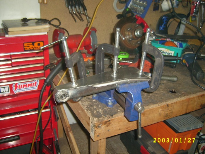
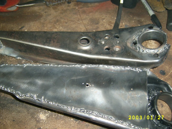
With this in mind I decide that I wanted to box the arms anyway but I was not doing so because I had to. I wanted to so I could practice welding and I really liked the finished look to. I only had some sheet metal to use but figured that it couldn't hurt. I traced one of the arms on my sheet metal and cut out the piece. Then I fit it in place and marked where I needed to trim and got a very good fit. Then I traced out the finished plate and cut out my second one. Before you box your arms you have two things to consider. You need to be able to access the under side for the strut rod nuts and the sway bar mount. I decided it would just be easier to weld the nuts for the strut rods to the arm and I came up with a easy way to get to the sway bar mount.
When you weld the nuts be sure to weld them in the right place so you can mount your strut rods. I didn't get a picture of this but if you mount your strut rods to the arms you will see that they bolt to only two of the four holes on a angel. Be sure you have this correct of you will be unhappy about going back and grinding out all your great welding. Another option for this is to not box that area of the LCA. Your choice. If I end up with problems I can still reach a wrench into the boxed arm and reach the nuts so this should be fine.
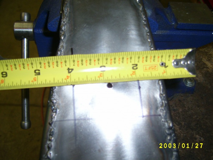
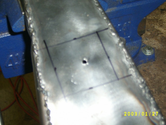
Now with both of these plates cut to perfection and the nuts welded in place, it was time to clamp them in place. I used 3 C clamps and lined everything up just right and went to town welding. When I was finished I drilled a hole from the top of the arm through the sway bar mounting hole. This left one little hole on the bottom of the arm. Then I measured one inch on each side of the drilled out hole to make a square. Then I cut it out with my cutting wheel. Now I have access to the sway bar mount with lots of room. Go over the edges with a file to take the sharp edges out.
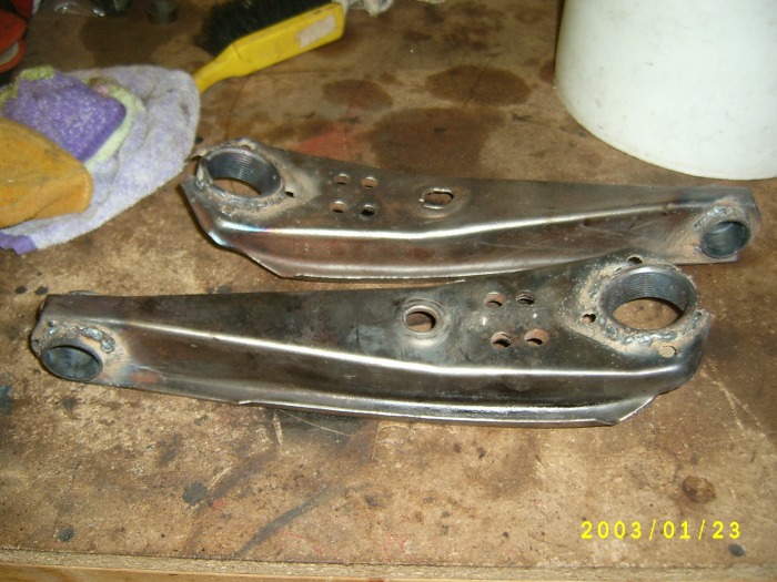
Welding is fun but it is a art and I am getting better at it. They don't look to bad now do they?

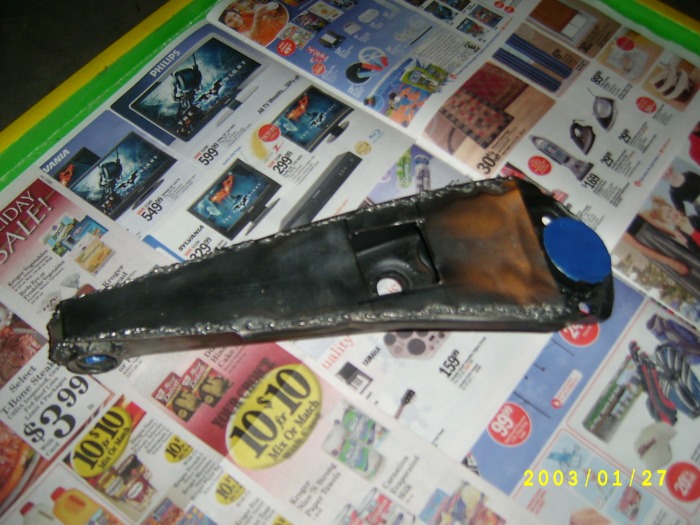
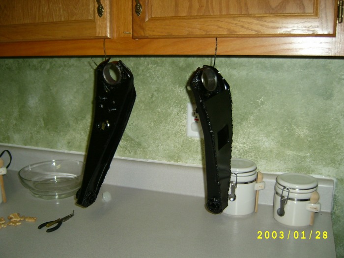
Now we are almost done. Time for paint. I tapped off the threaded sleeve for the ball joint. I don't want any paint to get in there. I also tapped off the bearings in the mounting sleeve. Then I gave some lite coats of semi-gloss rustoleum spray paint. Then when they were dry I put on a heavy coat. The Rustoleum stuff is pretty tough and should provide lots of protection for these awesome arms. I also inserted the strut rod bolts into the arms turning them pretty much all the way down so I could get a good coat of paint on them as well as keeping paint out of the threads of the nuts that I welded on under the arms. The last thing painted were the sleeves that go into the bearins. Dry and flip. We are almost done! Now to wait for them to dry.

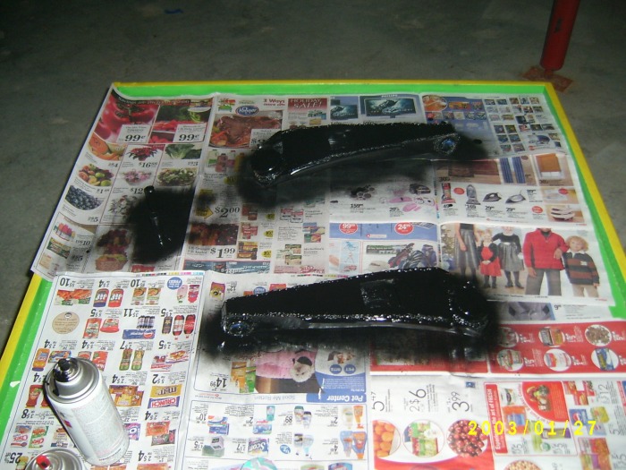
Now that the arms are all painted on both sides and the paint is dry and looking good it is time to put these all together. Pull of the tape that blocked off the areas we didn't want to paint. Insert the bolt sleeves into the bearings so that you are ready for the bolts.
Then the balljoints that we ordered need to be screwed into the arms from the bottom. Be sure they are tight but not over tight. Insert the grease nipple and slip the boot over the top, it just sort of sits on there. Then add the washer, the notched nut, the cotter pin, and grease the ball joint up well and you are done.
ROLLER LOWER CONTROL ARMS for the DIYer and these fit in with the Budget Restomod Mustang perfect. Pretty nice eh?

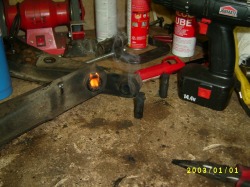
Alright. I posted my DIY article on a few forums and I got some great comments, and a few comments on my welding skills. I admit I am pretty green in the welding skill area so I took the suggestions of my fellow web car hobbyists and took my LCAs to the local hot rod shop and had the welder there go over the welds. $15 for safety and piece of mind. Since then I have started a few welding projects so I can improve my welding skills. Again, if you have doubts, source out the welding. The last two pictures above are after a good clean up, new welds, and fresh paint (in that order to).
MY COST:
Balljoints = $32.24
Balljiont Sleeves = $22.44
bearings = $12.56
bearing sleeves/retainers = $20.00
welding for sleeves = $15.00
TOTAL = $102.44 WHAT A DEAL!
One more reminder, the ball joints that are listed here (the same ones that OpenTracker uses) are the same for a pinto I believe. Anyway they are the same for a mustang with only the threads being longer. To over come this you need to use some high grade washers to fill in the gap. There is no problem with this and will keep things in place nice and tight.
